Thursday, September 14, 2023

Lesson 9- Control Servomotor


A servo motor is a specialized motor whose direction can be precisely set


This code uses the servo library. Libraries are code that adds additional functions to Arduino.

For example, to use a servo motor, we need to:

(1)    #include <Servo.h>. //include the servo library

(2) Servo myservo; // create servo object to control a servo

(3) myservo.attach(9); // attaches the servo on pin 9 to the servo object

(4) myservo.write(pos); write the servo position( 0 to 180)


#include <Servo.h>

Servo myservo; // create servo object to control a servo
// twelve servo objects can be created on most boards

int pos = 0; // variable to store the servo position

void setup() {
myservo.attach(9); // attaches the servo on pin 9 to the servo object
}

void loop() {
for (pos = 0; pos <= 180; pos += 1) { // goes from 0 degrees to 180 degrees
// in steps of 1 degree
myservo.write(pos); // tell servo to go to position in variable 'pos'
delay(15); // waits 15 ms for the servo to reach the position
}
for (pos = 180; pos >= 0; pos -= 1) { // goes from 180 degrees to 0 degrees
myservo.write(pos); // tell servo to go to position in variable 'pos'
delay(15); // waits 15 ms for the servo to reach the position
}
}

Lesson 8- LED Fade

 While the Arduino Uno cannot output a continuously varying(analog) voltage, it can simulate this using analogWrite

for example:

analogWrite(3, 128); //sets pin 3 to half-brightness.


,


int led = 9; // the PWM pin the LED is attached to
int brightness = 0; // how bright the LED is
int fadeAmount = 5; // how many points to fade the LED by

// the setup routine runs once when you press reset:
void setup() {
// declare pin 9 to be an output:
pinMode(led, OUTPUT);
}


// the loop routine runs over and over again forever:
void loop() {
// set the brightness of pin 9:
analogWrite(led, brightness);

// change the brightness for next time through the loop:
brightness = brightness + fadeAmount;

// reverse the direction of the fading at the ends of the fade:
if (brightness <= 0 || brightness >= 255) {
fadeAmount = -fadeAmount;
}
// wait for 30 milliseconds to see the dimming effect
delay(30);
}


Related:

Substitute a DC Motor for the LED

// the setup routine runs once when you press reset:
int motorPin = 12;

void setup() {
// initialize serial communication at 9600 bits per second:
Serial.begin(9600);
}

// the loop routine runs over and over again forever:
void loop() {
// read the input on analog pin 0:
int sensorValue = analogRead(A0);
// Convert the analog reading (which goes from 0 - 1023) to a voltage (0 - 5V):
float voltage = sensorValue * (5.0 / 1023.0);

analogWrite(motorPin, sensorValue / 4);

Serial.println(voltage);
}


Lesson 7- Read a Sensor(Photocell)


A photoresistor changes its resistance depending on how much light is falling on it. In the dark, its resistance can be 100K ohm or more; in light, it can decrease to 5K or less.


We will be reading the voltage on pin A0, using the analogRead function.


// the setup routine runs once when you press reset:
void setup() {
// initialize serial communication at 9600 bits per second:
Serial.begin(9600);
}

// the loop routine runs over and over again forever:
void loop() {
// read the input on analog pin 0:

int sensorValue = analogRead(A0);

// Convert the analog reading (which goes from 0 - 1023) to a voltage (0 - 5V):

float voltage = sensorValue * (5.0 / 1023.0);

// print out the value you read:

Serial.println(voltage);
}

Use the Serial Monitor to see the output voltage. Make sure the Baud Rate is the same as in the sketch(typically 9600).


Lesson 6: Multiple LEDS

 Try adding multiple LEDS, blinking in order:


Write code that turns multiple LEDs on and off- use the Copy and Paste functions to save time typing!

void setup() {
// initialize digital pin LED_BUILTIN as an output.
pinMode(7, OUTPUT);

pinMode(9, OUTPUT);


}

// the loop function runs over and over again forever
void loop() {

digitalWrite(7, HIGH); // turn the LED on (HIGH is the voltage level)
delay(1000); // wait for a second
digitalWrite(7, LOW); // turn the LED off by making the voltage LOW
delay(1000); // wait for a second

digitalWrite(9, HIGH); // turn the LED on (HIGH is the voltage level)
delay(1000); // wait for a second
digitalWrite(9, LOW); // turn the LED off by making the voltage LOW
delay(1000); // wait for a second
}

Lesson 5: The Blink Sketch- Light an LED


The resistor limits the amount of current


   Example Sketch: Blink

// the setup function runs once when you press reset or power the board
void setup() {
// initialize digital pin LED_BUILTIN as an output.
pinMode(LED_BUILTIN, OUTPUT);
}

// the loop function runs over and over again forever
void loop() {
digitalWrite(LED_BUILTIN, HIGH); // turn the LED on (HIGH is the voltage level)
delay(1000); // wait for a second
digitalWrite(LED_BUILTIN, LOW); // turn the LED off by making the voltage LOW
delay(1000); // wait for a second
}

In setup, we define the built-in LED(Pin 13) as an Output. You could assign another pin (2-12) as an output as well.


The check mark verifies that the code is grammatically correct, such as all statements end with semicolons, all functions are enc,osed in curly brackets {.   }. the right arrow uploads it to the board. Make sure you select the correct board and port.


Try changing the delay times in the code! Then change pin numbers!

Lesson 4: Structure of a Sketch(Program)


Statements are always followed by semicolons;

Example 1: Servo "Knob"

#include <Servo.h>

Servo myservo; // create servo object to control a servo

int potpin = A0; // analog pin used to connect the potentiometer
int val; // variable to read the value from the analog pin

void setup() {
myservo.attach(9); // attaches the servo on pin 9 to the servo object
}

void loop() {
val = analogRead(potpin); // reads the value of the potentiometer (value between 0 and 1023)
val = map(val, 0, 1023, 0, 180); // scale it for use with the servo (value between 0 and 180)
myservo.write(val); // sets the servo position according to the scaled value
delay(15); // waits for the servo to get there
}

Example 2: "Blink"

// the setup function runs once when you press reset or power the board
void setup() {
// initialize digital pin LED_BUILTIN as an output.
pinMode(LED_BUILTIN, OUTPUT);
}

// the loop function runs over and over again forever
void loop() {
digitalWrite(LED_BUILTIN, HIGH); // turn the LED on (HIGH is the voltage level)
delay(1000); // wait for a second
digitalWrite(LED_BUILTIN, LOW); // turn the LED off by making the voltage LOW
delay(1000); // wait for a second
}

The Arduino IDE(Integrated Development Environment) can be downloaded at:


There is also an online version at https://create.arduino.cc/editor. Once you log in, your code is saved in the cloud.

Lesson 3- Introduction to Arduino


Arduino UNO


Lesson 2: Components and Schematics


 Schematic Symbols: 

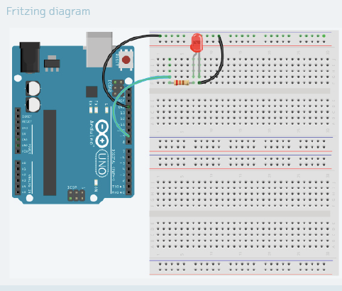
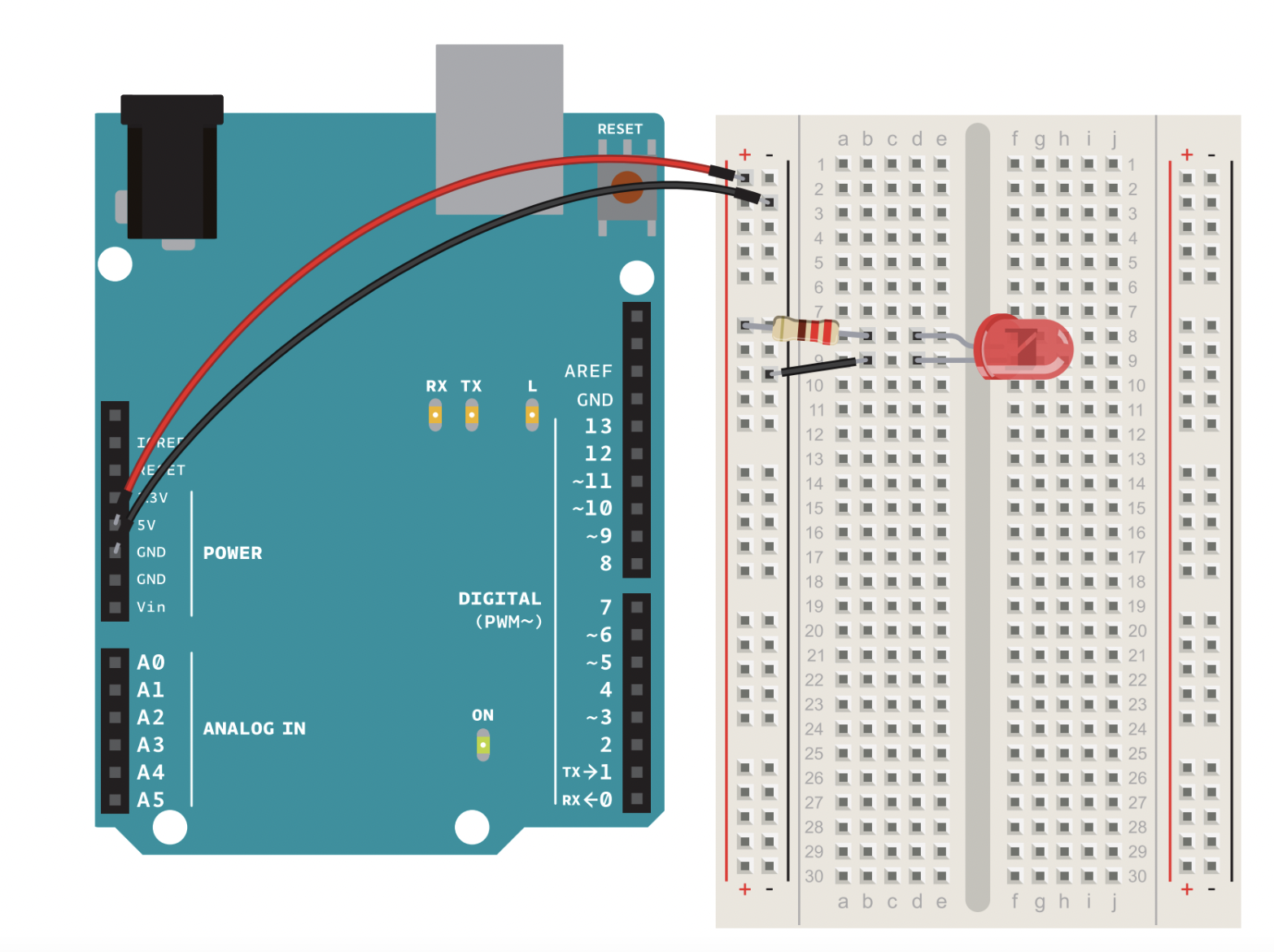
 A physical picture can be useful, but it often doesn't communicate the functioning of a circuit.

A schematic explains this much better:


Resistors


Activities:

  • Draw LED schematics
  • Practice reading color code on resistors


Solderless Breadboard:


Simple LED circuit:


Lesson 1: Tools


Soldering:


See More on tools at:


Activities:
  • Practice cutting and stripping wire
  • Soldering Practice Exercises
  • Measure voltage, resistance and current with a multimeter
Conventions:

#22 solid wire works best with solderless breadboards

Red wire should indicate power
Black wire should indicate ground

Wednesday, September 13, 2023

Lesson 0: Electricity Basics

 What is voltage? Voltage(V) is a measure of electrical force-how hard the electrons are being pushed. 

Arduino circuits typically run at 5V; newer devices use 3.3V.


Current is a measure of how many electrons are flowing, and is measured in Amperes or milliamperes(mA =1/1000 of an ampere). For example, LEDs run best at 20 mA; a small motor might draw 200 mA; a string of programmable LEDs might draw 800 mA. An Arduino can supply a maximum of 40 mA on its pins, so we need to use transistors or relays to control larger loads.


Resistance, measured on Ohms or kiloOhms(K), is a measure of how much current flow is resisted. The resistance of a resistor is marked using a color ode.


Ohm's Law: Voltage = Current x Resistance or V=I x R

LED Basics: